
In today’s world of Cloud Computing where all the "tin" and "wire" is managed by the cloud providers, the businesses need to focus on the cost and revenues more than anything else. However, there are still some scenarios where one would need to go ahead and implement the "tin" and "wire" setup. Today, I will walk you through the process which I followed to create a 2 node Windows Server 2004 Cluster on my laptop using VirtualBox. This is a great way to learn the tips and tricks of the game without actually having to go through a server setup inside a data center.
The first and foremost item needed to continue with this setup is a decent enough and capable laptop. Mine is a normal Intel Core i7 2nd Generation laptop with SSD drive and 16GB RAM. I have loaded on this VirtualBox 6.1 to create the server nodes.
Let’s start first with the high-level design on what our setup will look like and then drill down the bits that we need to download and finally configuring all these together to create our small test cluster.
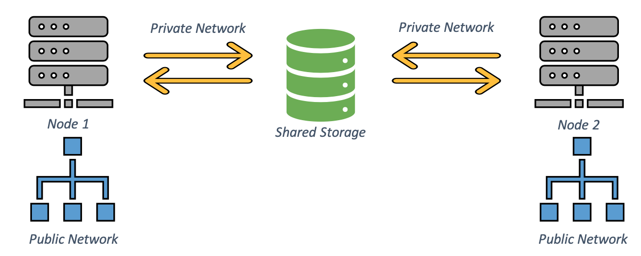
This is a simple 2 node cluster design with the following components:
- 2 Compute Nodes
- Shared Storage (disks accessible by both nodes at the same time)
- 2 Network segments (public network and private network)
Next step after the design is to list the software stack for these components:
- Compute nodes will run on Windows Server 2004
- 2 vCPUs
- 2GB RAM
- 50GB Boot Drive
- 2 x Network Interfaces (1 with Bridged network and 1 with Internet Network)
- Since we are using a laptop / standalone machine for the setup, we need a network-based storage solution to provide shared storage. I am using XigmaNAS for this. You can install and use any other solution which can provide you with a shared storage for your nodes.
- 2 vCPUs
- 3GB RAM
- 8GB Boot Drive
- 2 x Network Interfaces (1 with Bridged network and 1 with Internet Network)
With the software ready and downloaded, let’s start with the build. Below is the sequence I recommend.
- Create the NAS VM by booting it from the live CD for XigmaNAS (v12.1).
- Select option “9” to perform the install locally on the VM
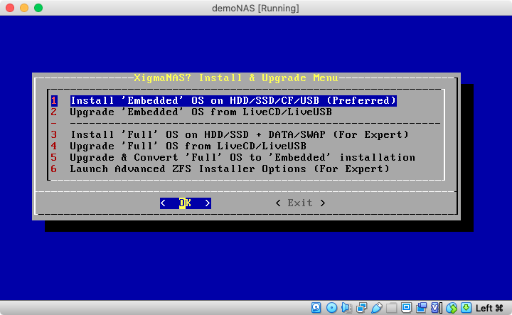
- Select option 1 “Embedded” OS install.
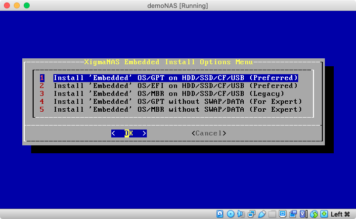
- Select option 1 again for installing using the GPT partitioning scheme
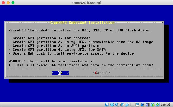
- Select “Ok” to continue with the install.
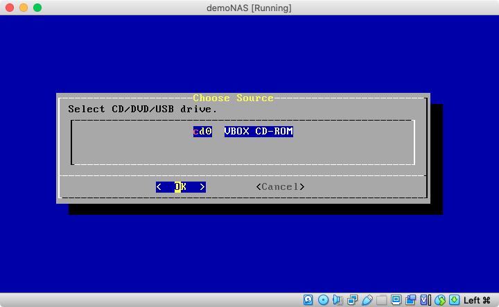
- Select “Ok” again to use the CD as the source.
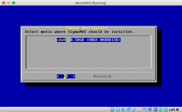
- Select “Ok” again to use the local disk as the target for the install.

- Accept the “2048M” as the size of the “root” partition. This is more than enough for our testing and is even the recommended size by XigmaNAS setup.
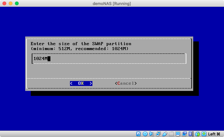
- Accept “1024M” as the size of the “swap” partition. These is one of the key partitions for any “*nix”-based setup. For those with Windows background, this is like the “Paging File” but created on its own special partition on the drive instead of residing on the “boot” partition.
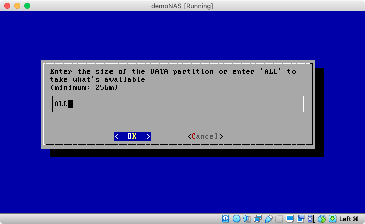
- Enter “ALL” on this screen to use the remaining space on the local disk for data partition to store our NAS data. This space will serve as the repository of our shared storage drive which we will create in the upcoming steps.
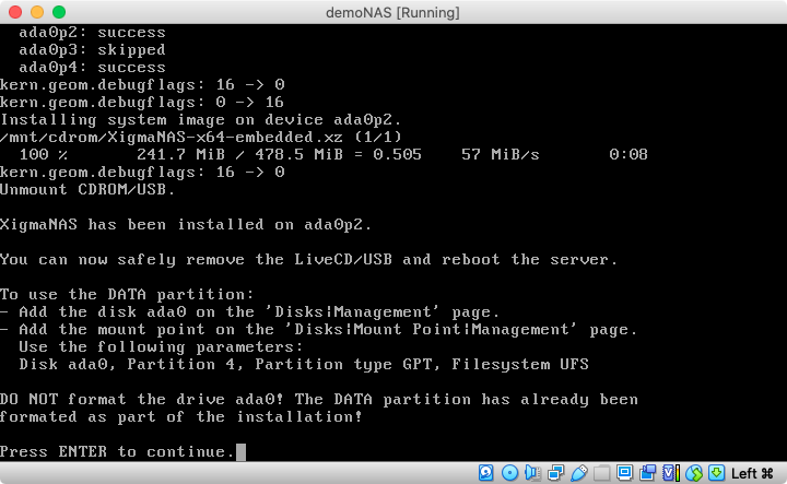
- Once the setup is complete, note down the number of the “DATA” partition as we will need it in later steps. Remove the live CD and reboot the VM to proceed with the shared storage setup.
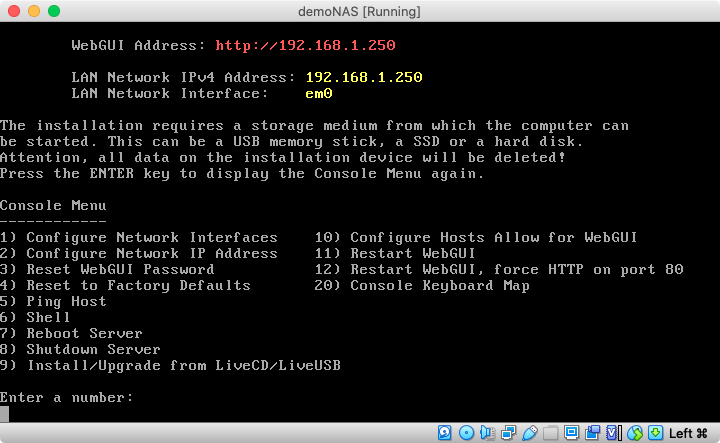
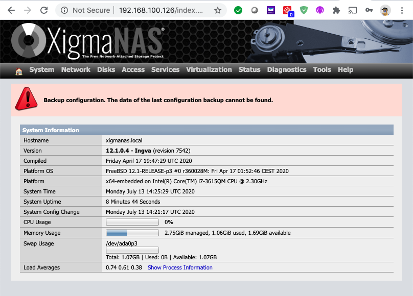
- On the first boot, the system will show the following on the console. Use the IP and open the web-browser to continue with the configuration.
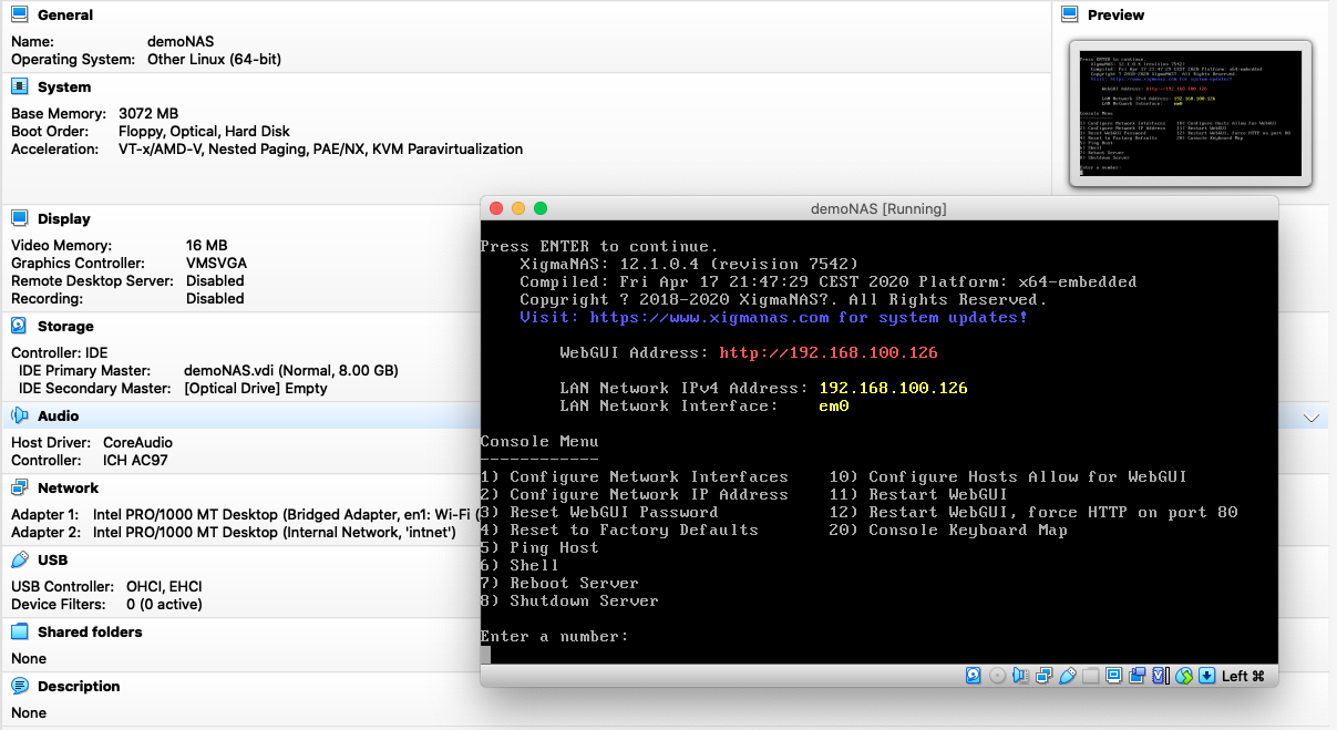
-
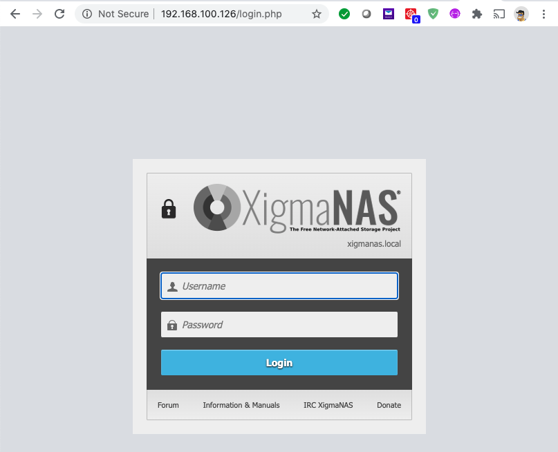
- Navigate in the browser to the stated WebUI Address on the console screen and login with the default username and password (admin / xigmanas)
- Once logged in, we will accomplish the following:
- Enable the second network card
- Enable the iSCSI Server
- Create data mount point
- Create extends on the data partition
- Create iscsi targets
- Configure default iscsi access rules
-
- Navigate to “Network” -> “Interface Management”
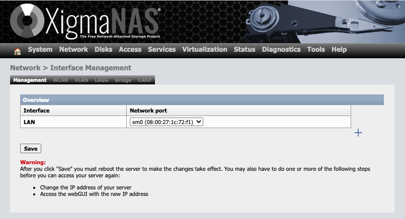
- Click on “+” icon on the right side of the screen, select the “em1” card for “OPT1” interface and clock on “Save” button.
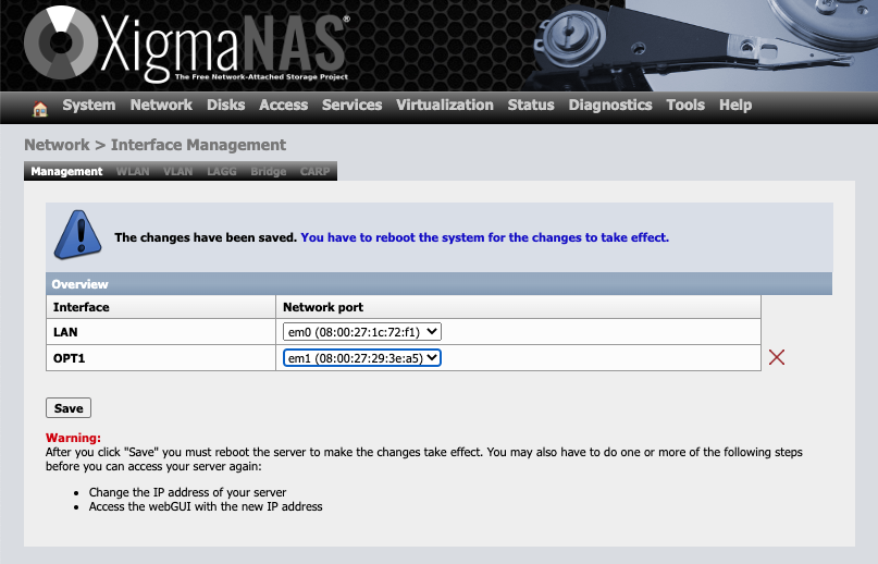
- Reboot the NAS system (System->Reboot)
- Once rebooted, login again and click on “Network” -> “OPT1”
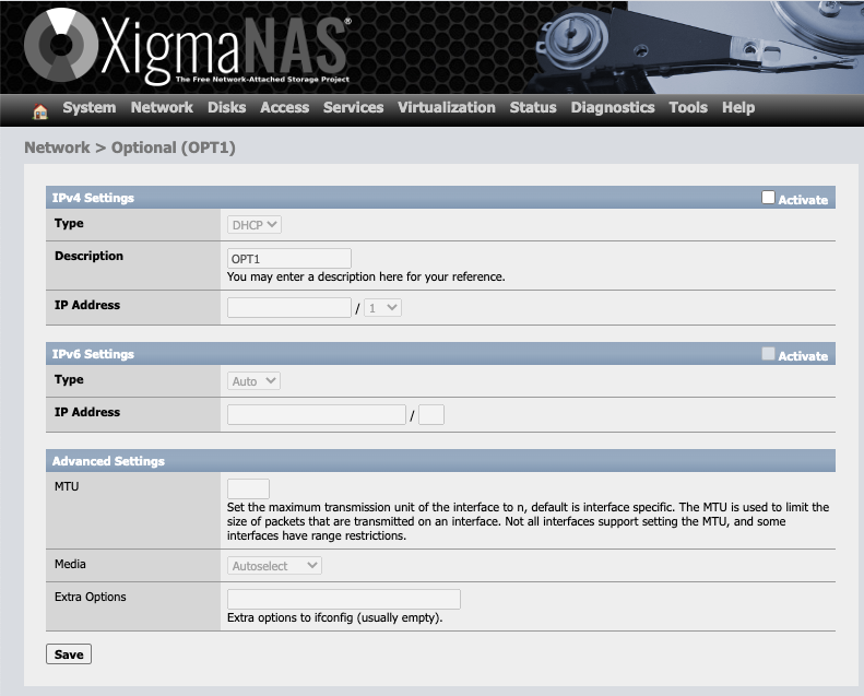
- Click on “Activate” for “IPv4 Settings”, change the type to “Static”, click on “Save” to enable the IP Address box, enter the IP address as “10.0.0.1” / ”24” and click “Save” again to save the settings.
- Reboot the NAS system (System->Reboot)
- Once rebooted, login again and click on “Disks” -> “Management”

- Click on “+” icon under the toolbox field
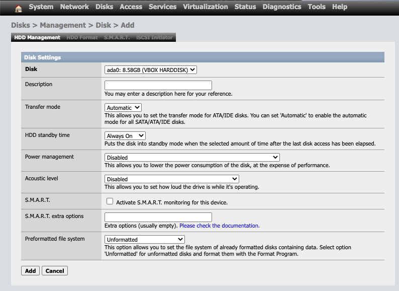
- Leave everything as default and ensure that “ada0” is selected in the disk dropdown. Click on “Add”
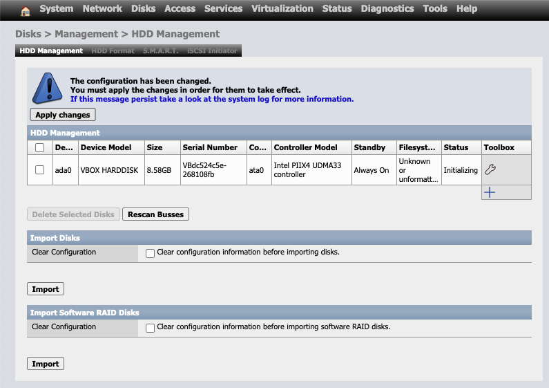
- Click on “Apply Changes”
- Click on “Disks” -> “Mount Point” menu options
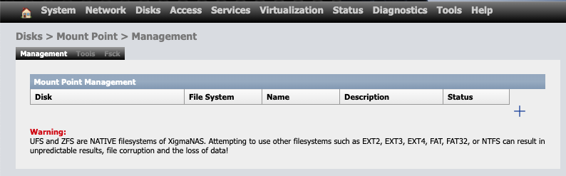
- Click on “+” icon towards the right of the screen.
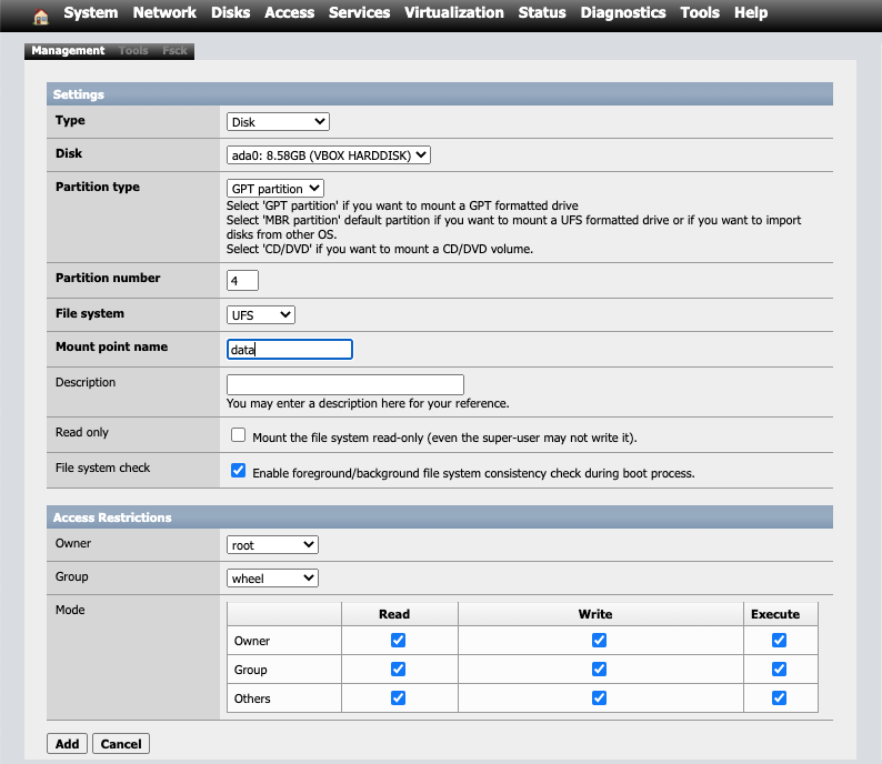
- Select “ada0” under the “Disk” dropdown and type “data” under “Mount point name”. You can provide any name you prefer. I prefer to call this mount point. Also ensure that the correct “Partition number” is specified. This is the same number we noted down after the installation was complete. If you have followed everything step by step till now, this should be “4”. Click “Add” to add this data mount point.
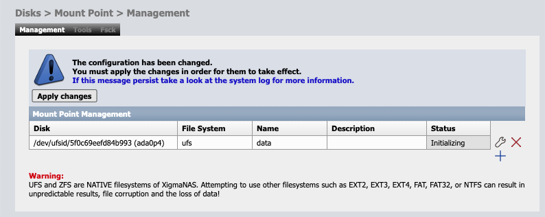
- Click on “Apply changes”
- Now we will configure “iSCSI” interface on the NAS. For that, click on “Services”->”iSCSI ISTGT” menu.
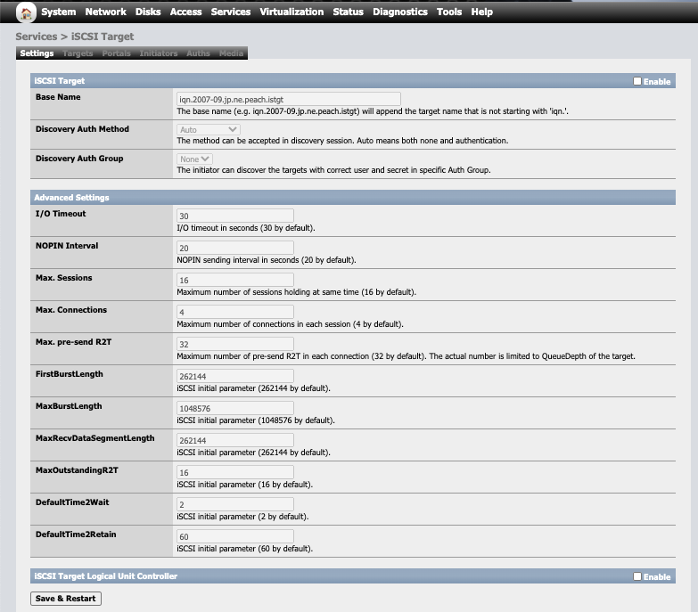
- Click on “Enable” on the “iSCSI Target” line and click on “Save & Restart”. If you want to customize the name of the target, you can do so under the “Base Name” field before clicking the “Save & Restart” button. I will leave this as default for this setup and continue.
- Click on “Portals” in the sub-menu items.
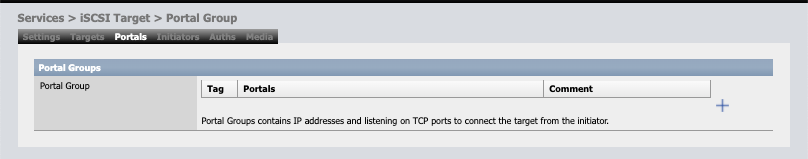
- Click on “+” icon on the right side and then click on “Add” with all the default options. This will setup the initiator portal for our iSCSI interface.
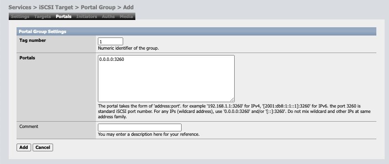
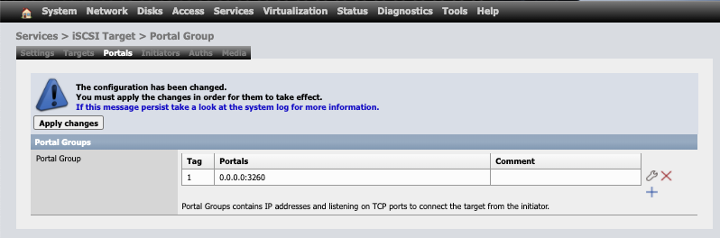
- Click on “Apply changes”
- Next click on “Initiators” in the sub-menu and then on the “+” icon on the right
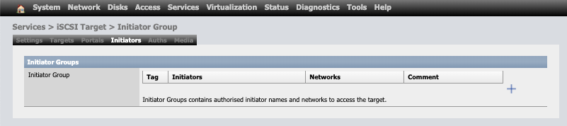
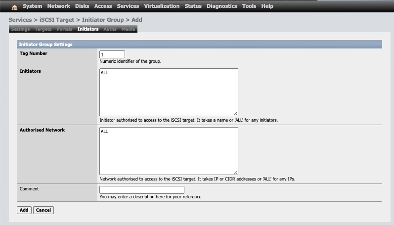
- Leave everything as default and click on “Add” and then “Apply changes”
- Next click on “Targets”
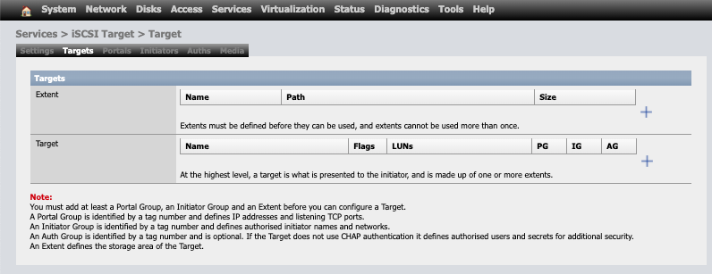
- Click on “+” icon under the “Extent” section
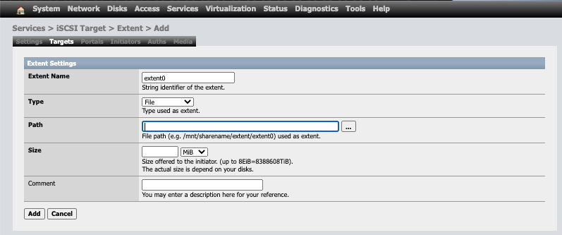
- Change the “Extent name” to “1TB01”, “Path” to “/mnt/data/1tb01”, “Size” to “1” and “TiB” and click on “Add”. Repeat the same to add a second extent as “1TB02”, “/mnt/data/1tb02” and “1”, “TiB”. Click on “Apply changes” to save these extents”
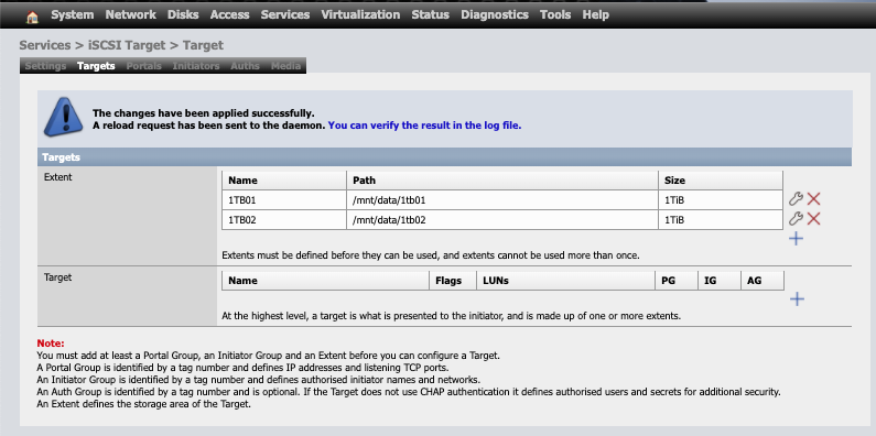
- Next step is to define the targets for these extents. For that click on the “+” icon under the “Target” section on the same page and add target for both the extents we defined in the previous steps. Includes these extents as LUN0 and LUN1 in the “Target” definition page
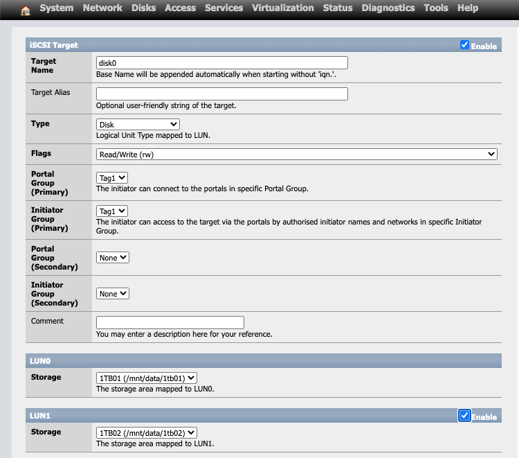
- Click “Add” and then “Apply changes”
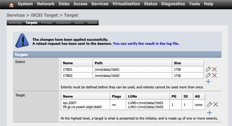
- This completes the NAS setup where we have defined a target with 2 LUNs to be used as cluster disks on our 2-node cluster which we will define now in the next steps. So, hang on a bit more and keep reading further for the steps to create this cluster.
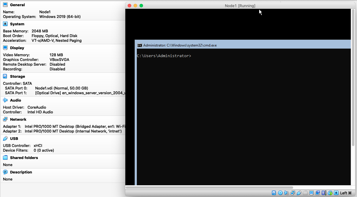
- Next create the first VM node using the Windows 2004 ISO. Install the “Standard Edition” and once complete, it should boot up in the command line interface.
- We will start with the basic server configuration and complete the below tasks:
- Rename the node (PowerShell Command)
Rename-Computer -NewName "Win2004"
-
-
- Configure a local DNS Suffix (needed to create clusters which are not part of a domain) (PowerShell Command)
-
Set-ItemProperty -Path "hklm:\system\currentcontrolset\services\tcpip\parameters" -Name "Domain" -Value "mylocal.net"
-
-
- Assign static IP to the cluster interface (PowerShell Command)
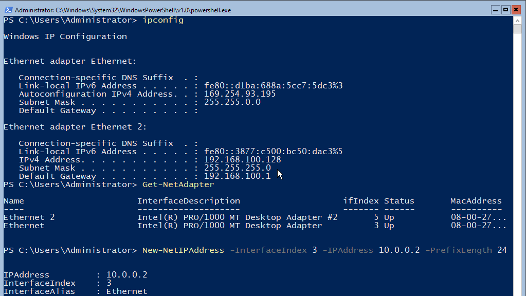
- Get the IP address configuration using the below command
- Assign static IP to the cluster interface (PowerShell Command)
-
IPconfig
-
-
-
- Identify the second card (connected to the internal network). This card would have a default IP starting with 169.
- Get the list of network cards using the below command
-
-
Get-NetAdapter
-
-
-
- Note the “ifindex” value of the card identified using the Ipconfig command and use that in the next command to assign a static IP to it.
-
-
New-NetIPaddress -InterfaceIndex 3 -IPAddress 10.0.0.2 -PrefixLength 24
-
-
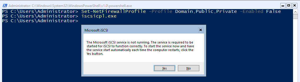
- Disable the firewall (PowerShell Command)
-
Set-NetFirewallProfile -Profile Domain,Public,Private -Enabled False
-
-
- Attach the NAS disks (Command Prompt)
- Run the command “iscsicpl.exe”
- It would prompt with a message stating the ISCSI service is not running. Click on “Yes” to enable the service and mark it as “Automatic” to start automatically whenever the server is rebooted.
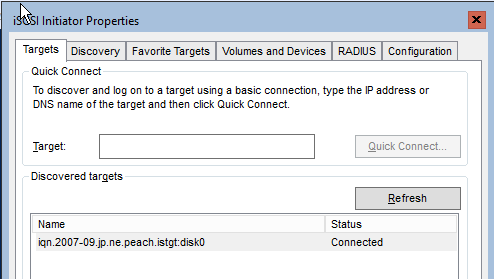
- On the iSCSI configuration screen, enter 10.0.0.1 as the target and click “Quick Connect” and then “Done”. If successfully connected, the NAS will show up in the “Discovered targets”.
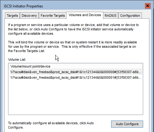
- Click on “Volumes and Devices” -> “Auto Configure”. This should load both the LUNs that we created earlier on the NAS administration portal.
- Click “Ok” to close this iSCSI configuration application and reboot the server using command “shutdown /r /t 0”
- Next we will configure these iSCSI disks and make them visible to the Operating System and Cluster Manager. For this we will use “DiskPart” command.
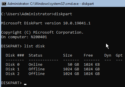
- Run “DiskPart.exe”
- Type “List Disk”
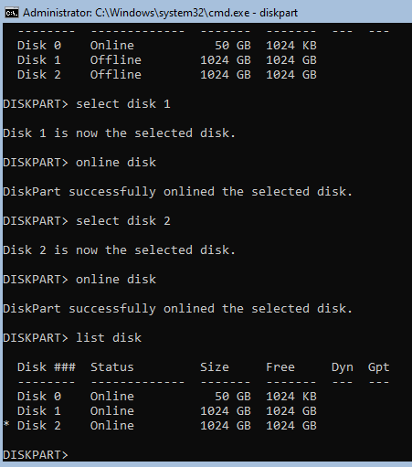
- Bring the Disk 1 and Disk 2 online using commands “Select disk 1”, “online disk”, “select disk 2”, “online disk” and list the disks again using “list disk”
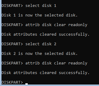
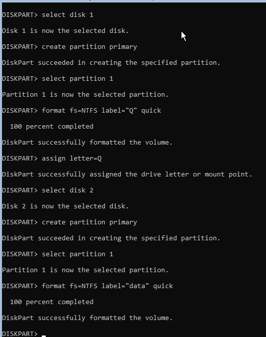
- By default, all disks brought online will be marked as read-only. Next we will mark then as read-write, create the partition and format it using NTFS. For the first disk we will assign it as “Q” drive and for the second disk we will not assign any drive letter as we will use this as a “Clustered Shared Volume” which will be available on both the nodes at the same time under the path “C:\ClusteredVolumes” as a junction point.
- The commands for clearing read-only attributes are “select disk 1”, “attrib disk clear readonly”, “select disk 2”, “attrib disk clear readonly”
- Next create the partitions using commands “select disk 1”, “create partition primary”, “select partition 1”, “format fs=NTFS label=”Q” quick”, “assign letter=Q”, “select disk 2”, “create partition primary”, “select partition 1”, “format fs=NTFS label=”data” quick”
- This completes the disk operations and now both “quorum” and “data” disks are available to the OS and ready for cluster setup. Let’s start with the cluster setup.
- Attach the NAS disks (Command Prompt)
-
- Now that the VM is ready and configured with network adapters and storage disks, the next step is to install the Cluster feature and run the cluster validation task to check the readiness of the VM to host a cluster. All the commands below are to be executed inside the PowerShell session as “Administrator” with elevated permissions.
-
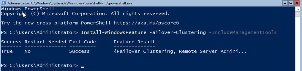
- Install the cluster feature using command “Install-WindowsFeature Failover-Clustering -IncludeManagementTools”
- Create hosts entries. Since we are setting this up without a domain, we need to rely on “hosts” file for the name lookups. Add the below entries to the “hosts” file using “notepad” running from an elevated session.
- 10.0.0.2 N200401 N200401.mylocal.net
- 10.0.0.3 N200402 N200402.mylocal.net
- 10.0.0.10 AppCluster AppCluster.mylocal.net
- Run the cluster validation process using command “Test-Cluster -Node N200401.mylocal.net”
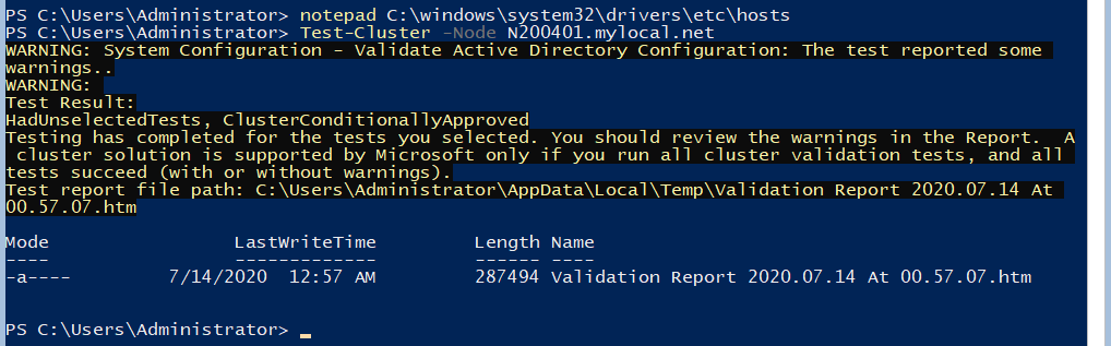
- The test will report warnings about “Active Directory” which is true as we do not have an AD setup and the cluster is “Conditionally Approved”. We will proceed with this as it is good enough for our testing.
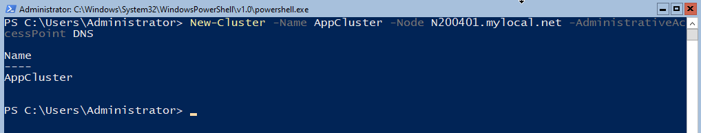
- Once the test is complete, we will create the cluster using command “New-Cluster -Name AppCluster -Node N200401.mylocal.net -AdministrativeAccessPoint DNS”
- Once the cluster is created, let us check which network cards got assigned to what roles on the cluster. For that run the command “Get-ClusterNetworkInteface” and “Get-ClusterNetwork”.
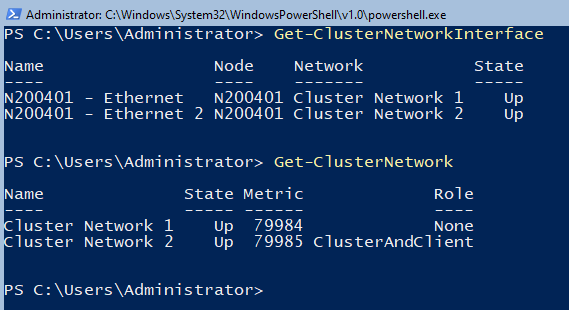
- Based on the details from the above commands, the network cards are incorrectly assigned. We need to fix this. The “Ethernet” is the which we intend to use for the “ClusterAndClient” communications. So, let’s change this before we move further.
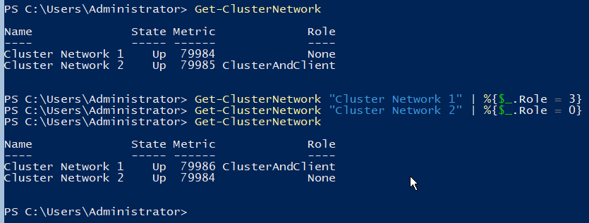
- First step here would be to mark “Cluster Network 1” as carrying both Cluster and Client communication. Once that is done, we mark “Cluster Network 2” as “None”. To accomplish this, we execute the commands “Get-ClusterNetwork “Cluster Network 1” | %{$_.Role = 3}” and “Get-ClusterNetwork “Cluster Network 2” | %{$_.Role = 0}”
- Next we will configure the static IP on the “Cluster IP Address” resource. To do this execute the command “Get-ClusterResource “Cluster IP Address” | Set-ClusterParameter -Multiple @{“Network”=”Cluster Network 1”;”Address”=”10.0.0.10”;”SubnetMask”=”255.255.255.0”;”EnableDhcp”=”0”}”. Once set, stop and start the cluster resource for the changes to take effect.
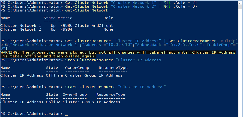
- Since the IP was stopped and started, we will start the “Cluster Name” resource also using command “Start-ClusterResource “Cluster Name””
- This will bring our cluster to a healthy state with a single node.
- Next we will add the disks to the cluster.
-
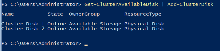
- To start with adding disks to the cluster, we need to first check the list of available disks which can be added to the cluster.
- This can be achieved by the command “Get-ClusterAvailableDisk”
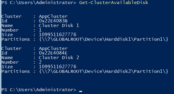
- Next, pipe the output of this command to “Add-ClusterDisk” to add both the available disks to the cluster.
- We will assign one of these disks as “Quorum”. To identify it in the future, we will start by first renaming the resource and then adding it as a quorum.
- To rename the disk, use the command “Get-ClusterResource “Cluster Disk 1” | %{$_.Name=”Quorum”}”
- To add it as quorum, execute the command “Set-ClusterQuorum -NodeAndDiskMajority “Quorum””. Here the name “Quorum” is what has been set in the previous rename command. So, if you have named it something else, use that in this command.
- Last, we will add the second disk as a “Clustered Shared Volume”. For this, the command is “Add-ClusterSharedVolume -Name “Cluster Disk 2””
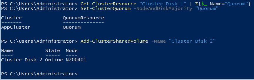
- This completes the single node cluster setup where we have a cluster name, IP, quorum and a clustered disk available.
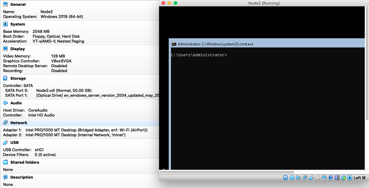
- The next step now is to create the second node and add it to the cluster. For this follow the same steps we used to create the first node N200401. We will call it N200402 and complete till the step of creating the hosts file and installing the cluster feature. Also, skip the steps of creating partitions and formatting the partitions on the NAS disks as they have already been created during the first node setup.
- Ensure that the password for the local administrator account is the same as the first node. The cluster will use that to communicate between the nodes. If the passwords are different, the nodes will not be able to communicate correctly and the cluster will fail to work as intended.
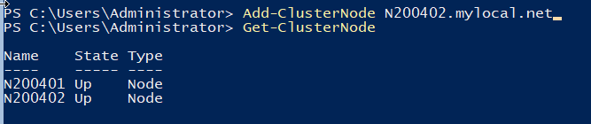
- Once the OS, network and disks are configured similar to node 1, add this node to the cluster by running the command from node 1 “Add-ClusterNode N200402.mylocal.net” and view the status of the node by running command “Get-ClusterNode”
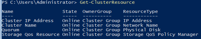
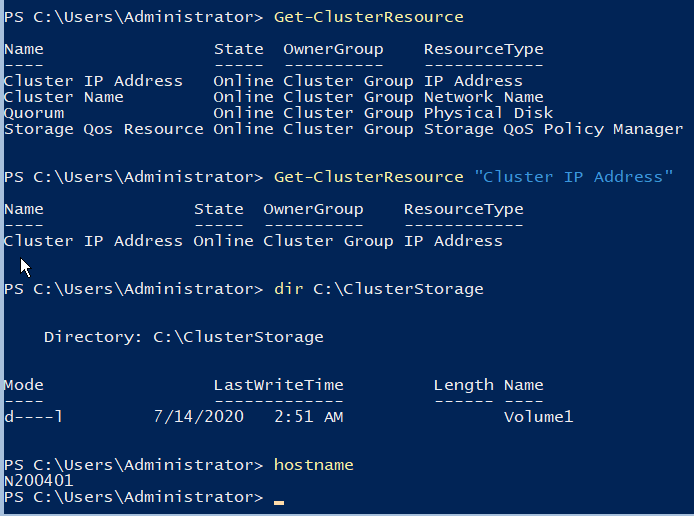
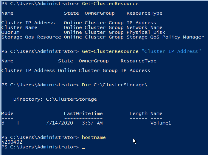
- Verify all the resources also by running the command “Get-ClusterResource” which should list all resources as “Online”. To further confirm the status of the node 2, check the clustered volume folder for the existence of the “Clustered Shared Disk”
- One more test will be to failover the node from one to another. For this we run the command “Move-ClusterGroup “Cluster Group””.
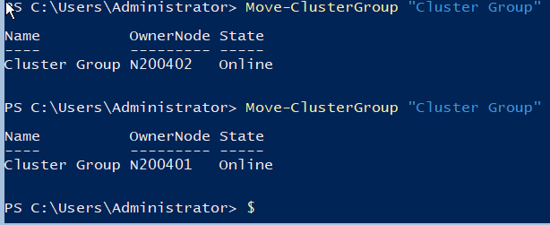
This completes the setup and now you have a working 2 node Windows Failover Cluster, all created from the command line using PowerShell and a few other regular commands.
PDF for this article- 217 views